- 您现在的位置:买卖IC网 > Sheet目录1214 > EVAL-ADE7754EBZ (Analog Devices Inc)BOARD EVALAUTION FOR ADE7754
�� ��
��
��ADE7754�
�APOS[11:0]�
�I�
�HPF�
�SGN� SGN� SGN� SGN� SGN� 2� 10�
�2� 4�
�2� 3�
�2� 2�
�2� 1�
�2� 0�
�ACTIVE� POWER�
�SIGNAL� –� P�
�CURRENT� SIGNAL� –� i(t)�
�–100%� TO� +100%� FS�
�28F5C2h�
�00h�
�D70A3Eh�
�1V/GAIN1�
�MULTIPLIER�
�24�
�LPF2�
�28�
�+�
�12�
�D1B717h�
�V�
�1�
�INSTANTANEOUS�
�POWER� SIGNAL� –� p(t)�
�AWG�
�VOLTAGE� SIGNAL� –� v(t)�
�–100%� TO� +� 100%� FS�
�28F5h�
�00h�
�1V/GAIN2�
�D70Bh�
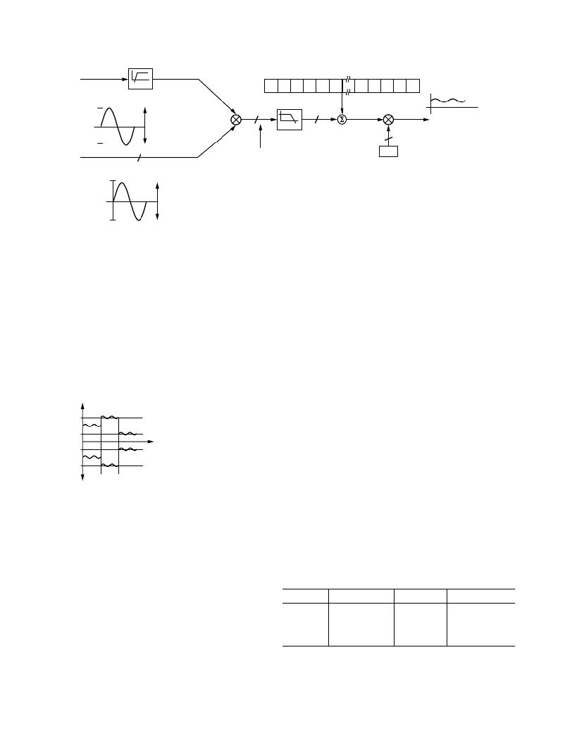
�Figure� 24.� Active� Power� Signal� Processing�
�Figure� 24� shows� the� signal� processing� in� each� phase� for� the�
�active� power� in� the� ADE7754.�
�Figure� 25� shows� the� maximum� code� (hexadecimal)� output�
�range� of� the� active� power� signal� (after� AWG).� Note� that� the�
�output� range� changes� depending� on� the� contents� of� the� active�
�power� gain� and� watt� gain� registers.� See� the� Current� Channel�
�ADC� section.� The� minimum� output� range� is� given� when� the�
�active� power� gain� and� watt� gain� registers� contents� are� equal� to�
�800h,� and� the� maximum� range� is� given� by� writing� 7FFh� to� the�
�active� power� gain� and� watt� gain� registers.� These� can� be� used� to�
�calibrate� the� active� power� (or� energy)� calculation� in� the�
�ADE7754� for� each� phase� and� the� total� active� energy.� See� the�
�Total� Active� Power� Calculation� section.�
�Reverse� Power� Information�
�The� ADE7754� detects� when� the� current� and� voltage� channels�
�of� any� of� the� three� phase� inputs� have� a� phase� difference� greater�
�than� 90� °� (i.e.,� |� A� |� or� |� B� |� or� |� C� |� >� 90� °� ).� This� mechanism�
�can� detect� wrong� connection� of� the� meter� or� generation� of�
�active� energy.�
�The� reverse� power� information� is� available� for� Phase� A,� Phase� B,�
�and� Phase� C,� respectively,� by� reading� Bits� 12� to� 14� of� the� CFNUM�
�register.� See� Table� XI.� The� state� of� these� bits� represents� the�
�sign� of� the� active� power� of� the� corresponding� phase.� Logic� 1�
�corresponds� to� negative� active� power.�
�The� AENERGY� phase� selection� bits� (WATSEL� bits� of� the�
�WATMode� register)� enable� the� negative� power� detection� per�
�ACTIVE�
�POWER�
�VOLTAGE� CHANNEL�
�CURRENT� CHANNEL�
�0.5V/GAIN2�
�0.5V/GAIN1�
�phase.� If� Phase� A� is� enabled� in� the� AENERGY� accumulation,�
�Bit� 5� of� WATMode� register� sets� to� Logic� 1� and� the� negative�
�power� detection� for� Phase� A—Bit� 12� of� CFNUM� register—�
�13A92A4h�
�D1B717h�
�68DB8Ch�
�0000000h�
�972474h�
�2E48E9h�
�+� 150%� FS�
�+� 100%� F5�
�+� 50%� FS�
�AAPGAIN[11:0]� OR� AWGAIN[11:0]�
�–� 50%� FS�
�–� 100%� FS�
�indicates� the� direction� of� the� active� energy.� If� Phase� A� is�
�disabled� in� the� AENERGY� register,� the� negative� power� bit� for�
�Phase� A� is� set� to� Logic� 0.�
�TOTAL� ACTIVE� POWER� CALCULATION�
�EC56D5Ch�
�000h�
�7FFh�
�800h�
�–� 150%� FS�
�The� sum� of� the� active� powers� coming� from� each� phase� provides�
�the� total� active� power� consumption.� Different� combinations� of�
�Figure� 25.� Active� Power� Calculation� Output� Range�
�Power� Offset� Calibration�
�The� ADE7754� also� incorporates� an� active� offset� register� on� each�
�phase� (AAPOS,� BAPOS,� and� CAPOS).� These� are� signed� twos�
�complement� 12-bit� registers� that� can� be� used� to� remove� offsets�
�in� the� active� power� calculations.� An� offset� may� exist� in� the�
�power� calculation� because� of� crosstalk� between� channels� on� the�
�PCB� or� in� the� IC� itself.� The� offset� calibration� allows� the� con-�
�tents� of� the� active� power� register� to� be� maintained� at� zero� when�
�no� power� is� being� consumed.�
�the� three� phases� can� be� selected� in� the� sum� by� setting� Bits� 7� and�
�6� of� the� WATMode� register� (mnemonic� WATMOD[1:0]).�
�Figure� 26� demonstrates� the� calculation� of� the� total� active� power,�
�which� depends� on� the� configuration� of� the� WATMOD� bits� in�
�the� WATMode� register.� Each� term� of� the� formula� can� be� disabled�
�or� enabled� by� setting� WATSEL� bits� respectively� to� Logic� 0� or�
�Logic� 1� in� the� WATMode� register.� The� different� configurations�
�are� described� in� Table� I.�
�Table� I.� Total� Active� Power� Calculation�
�One� LSB� in� the� active� power� offset� register� is� equivalent� to� one�
�WATMOD� WATSEL0�
�WATSEL1�
�WATSEL2�
�LSB� in� the� 28-bit� energy� bus� displayed� in� Figure� 24.� Each�
�time� power� is� added� to� the� internal� active� energy� register,� the�
�content� of� the� active� power� offset� register� is� added.� See� the�
�Total� Active� Power� Calculation� section.� Assuming� the� average�
�0d�
�1d�
�2d�
�V� A�
�V� A�
�V� A�
�I� A� *�
�(I� A� *� –I� B� *� )�
�(I� A� *� –I� B� *� )�
�+� V� B�
�+0�
�+0�
�I� B� *�
�+� V� C�
�+� V� C�
�+� V� C�
�I� C� *�
�(I� C� *� –I� B� *� )�
�I� C� *�
�value� from� LPF2� is� 8637BCh� (8,796,092d)� with� full� ac� scale�
�inputs� on� current� channel� and� voltage� channel,� then� one� LSB� in�
�the� LPF2� output� is� equivalent� to� 0.011%� of� measurement� error�
�at� –60� dB� down� of� full� scale.� See� the� Calibration� of� a� 3-Phase�
�Meter� Based� on� the� ADE7754� Application� Note� AN-624.�
�Note� that� I� A� *� ,� I� B� *� ,� and� I� C� *� represent� the� current� channel�
�samples� after� APGAIN� correction� and� high-pass� filtering.�
�–18� –�
�REV.� 0�
�发布紧急采购,3分钟左右您将得到回复。
相关PDF资料
EVAL-ADE7755ZEB
BOARD EVALUATION FOR AD7755
EVAL-ADE7758ZEB
BOARD EVAL FOR AD7758
EVAL-ADE7759EBZ
BOARD EVALUATION FOR ADE7759
EVAL-ADE7762EBZ
BOARD EVALUATION FOR ADE7762
EVAL-ADE7763ZEB
BOARD EVALUATION FOR ADE7763
EVAL-ADE7816EBZ
BOARD EVALUATION FOR ADE7816
EVAL-ADE7878EBZ
BOARD EVAL FOR ADE7878
EVAL-ADE7880EBZ
BOARD EVAL FOR ADE7880
相关代理商/技术参数
EVAL-ADE7755EB
制造商:Analog Devices 功能描述:EVAL BOARD ENERGY METERINGW/PULSE OUTPUT - Bulk
EVAL-ADE7755EBZ
制造商:AD 制造商全称:Analog Devices 功能描述:Energy Metering IC with Pulse Output
EVAL-ADE7755EBZ1
制造商:AD 制造商全称:Analog Devices 功能描述:Energy Metering IC with Pulse Output
EVAL-ADE7755ZEB
功能描述:BOARD EVALUATION FOR AD7755 RoHS:是 类别:编程器,开发系统 >> 评估演示板和套件 系列:- 标准包装:1 系列:- 主要目的:电信,线路接口单元(LIU) 嵌入式:- 已用 IC / 零件:IDT82V2081 主要属性:T1/J1/E1 LIU 次要属性:- 已供物品:板,电源,线缆,CD 其它名称:82EBV2081
EVAL-ADE7756EB
制造商:Analog Devices 功能描述:EVAL BD DOCUMENTATION ADE7756 ENERGY METERING IC - Bulk 制造商:Rochester Electronics LLC 功能描述:
EVAL-ADE7757AEBZ
制造商:Analog Devices 功能描述:EVALUATION BOARDS - Bulk
EVAL-ADE7757EB
制造商:Analog Devices 功能描述:EVAL BOARD ENERGY METERINGW/PULSE OUTPUT - Bulk
EVAL-ADE7758ZEB
功能描述:BOARD EVAL FOR AD7758 RoHS:是 类别:编程器,开发系统 >> 评估演示板和套件 系列:* 标准包装:1 系列:PSoC® 主要目的:电源管理,热管理 嵌入式:- 已用 IC / 零件:- 主要属性:- 次要属性:- 已供物品:板,CD,电源